
Official websites use .gov
A .gov website belongs to an official government organization in the United States.
Secure .gov websites use HTTPS
A lock (
) or https:// means you’ve safely connected to the .gov website. Share sensitive information only on official, secure websites.
System for infrared spectral emittance of materials
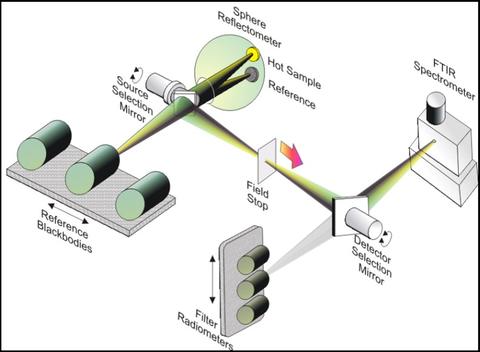
This facility enables the measurement of spectral emittance using the direct method of radiance comparison of the sample with a blackbody reference source. Spectral emissivity is a key physical property in the determination of radiation transfer and balance. Numerous industrial and scientific applications, such as remote sensing and single- and multi-band pyrometry, require its accurate determination.
The sample emittance is determined through a series of measurement steps. The first step is a measurement of the sample's hemispherical-directional reflectance at the measurement temperature and at a single wavelength matched to the filter radiometer. A diode laser or broadband source input to the integrating sphere, is selected based on the temperature and rough emittance value of the sample. The reflectance is obtained via comparison to a calibrated standard.

The second step is a relative radiance measurement of the sample to a blackbody at the same wavelength. The integrating sphere is removed for the second step. The temperature is then calculated from the results of these two steps. This procedure has the benefit of obtaining the temperature of the sample from the region on the sample identical to that for which the infrared spectral emittance is measured. It also makes use of the steep short wavelength edge of the Planck function for sensitive (and higher accuracy) temperature measurement.
Finally, the Fourier transform infrared spectrometer is used to compare the sample spectral radiance to that of the reference blackbody source as a ratio, and the sample emittance is obtained from the ratio and Planck's Law using the sample and blackbody temperatures.
Alternatively, spectral directional emittance can be determined indirectly from reflectance and transmittance measurements described in Infrared Spectrophotometry. These capabilities have limits of temperature, measurement geometry and sample type.
Specifications/Capabilities
The facility consists of a set of reference blackbody sources mounted on a motorized stage for selection; interchangeable sample heater/mounts on motorized translation and rotation stages; a removable visible/near-infrared integrating sphere for measuring the sample temperature above 500 K; low scatter interface optics to image the 3 mm to 5 mm central region of the sample or blackbody source onto a water cooled field stop; the field stop is re-imaged onto either a Fourier transform spectrophotometer equipped with beamsplitters and detectors to cover a spectral range from the visible through the far infrared or a set of filter radiometers mounted on a motorized translation stage for temperature scale transfer between the blackbody sources and for sample temperature determination (together with the integrating sphere); a sectored purge enclosure for the entire beam path; electrical supply, signal, purge gas (Ar, or N2), and cooling water subsystems; control of system elements and data processing via several PC computers using LabView software programs.
Each blackbody contains calibrated platinum resistance thermometer (PRT) or thermocouple (TC) temperature sensors. These are used to control and monitor changes in the blackbody temperature. For absolute temperature determination, two fixed point BB furnaces with interchangeable crucibles (containing Ag, Al, Zn, Sn and In) are used. Filter radiometers (with filters at 650 nm, 900 nm, 1550 nm, and 2400 nm) are used to transfer the scale from the fixed points to 4 variable temperature blackbody's covering a temperature range of 250 K to 1400 K. The spectral emissivities of the blackbodies have been calculated using a Monte Carlo ray tracing algorithm with input of the measured spectral reflectance of the cavity wall materials or coatings.