The Construction of the SURF III Magnet
The south backleg is guided into position on the lower yoke. The two backlegs support the upper yoke assembly and provide a return path for the magnetic flux generated by the magnet.
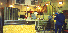
One block of the upper yoke is cleaned and prepared for placement. Since these blocks rest on top of the backlegs, the lower face is the presicely machined surface and must be cleaned prior to placement.
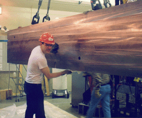
The first block of the upper yoke is being prepared for installation. It will be joined by four others and bolted into a single assembly. This five-block construction is identical to the lower yoke. Assembling the upper yoke was much easier than the lower yoke since the backlegs provide a much flatter surface than the floor.
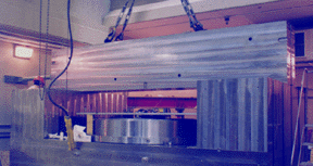
The final block of the upper yoke assembly is lowered into place. After aligning this block to the others, the five upper yoke blocks were bolted into a single piece weighing 68,000 kg (75 tons).
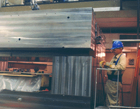
The completed upper yoke rests on the backlegs. The lower pole piece can be seen in position in the middle of the magnet. On the floor, the upper pole awaits installation.
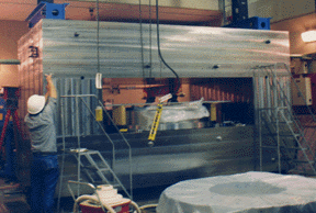
Both pole pieces have been installed. The poles have been aligned in the center of the magnet assembly to within 25 µm (0.001 in). Pictured on the left is Lee Greenler, the mechanical engineer who performed the detailed design of the SURF III magnet for the project prime contractor PSL Engineering and Instrumentation.
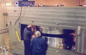
The yellow main coils have been installed around the pole pieces. The upper yoke assembly was moved aside and the lower main coil was placed around the lower pole. Then the upper main coil was placed in its location and the upper pole (on the yoke assembly) was lowered into the coil. In this picture, one portion of the lower yoke has been painted with a light blue rust-inhibiting paint.
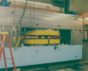
The final step of the magnet assembly process was the installation of the trim coils on the pole faces. These small coils will be used during injection to control eddy currents formed by ramping up the magnetic field. The mustard colored surfaces have been coated with primer, but not yet painted blue.
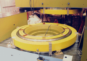
This page is online for historical purposes and will not be updated. Any questions should be sent to rvest [at] nist.gov (Rob Vest).
Contacts
-
(301) 975-3992

